
Individually Definable Travel Ranges
The working envelope and axis travel are tailored to your actual workpiece dimensions – not to a catalog size.
Portal Milling Machine
At assemblean, we do not look at the machine in isolation. We develop the solution based on your specific manufacturing task: component geometry, material, batch size, accuracy requirements, machining time and the desired degree of automation determine which machine kinematics make technical and economic sense.
Machine design, controls and process engineering all come from a single source – from the first technical assessment through to commissioning.

Service overview
A portal milling machine is a CNC milling machine in which the milling head is guided along a portal-like machine structure. The workpiece is located inside or beneath this portal. Depending on the design, either the portal moves over the workpiece, or the workpiece is moved through the portal on a traveling machine table.
The key advantage of this design lies in the large usable working envelope. This makes portal milling machines particularly suitable for large-surface components, plates, machine components, molds, profiles and structural parts.
The CNC control moves the milling spindle and axes based on a previously programmed tool path, which is typically generated from a CAD model in CAM software and passed to the machine control via a post-processor. Depending on the machine kinematics, the tool can machine the component in three axes or – with more advanced machine concepts – additionally via rotary and swivel axes.
Core Components
The key components of a portal milling machine include:
The working envelope and axis travel are tailored to your actual workpiece dimensions – not to a catalog size.
From simple facing and pocket milling to the simultaneous machining of complex freeform surfaces.
Aluminum, steel, plastics and composite materials each place their own demands on rigidity, spindle and cooling.
Clamping system, automatic tool changer and metrology are planned as one interconnected process system.
From manual operation to robot-assisted, unmanned production.
Machine design, control technology and process engineering are developed at assemblean in one continuous engineering process.
In practice, these terms are sometimes used synonymously. Which design makes technical sense depends less on the designation than on workpiece size, workpiece weight, machining forces and the required dynamics.
| Analysis parameter | Portal Milling Machine | Gantry Mill | Gantry Milling Machine | Portal Mill |
|---|---|---|---|---|
| Meaning | General technical term for any milling machine with a portal structure | Shorter, colloquial term | Design in which the portal moves over a stationary workpiece | Term for large portal machines on an industrial scale |
| Typical Usage | Technical literature and mechanical engineering in general | Mainly for smaller CNC systems | When the motion of the portal is to be emphasized | In industrial special-purpose machine building |
| Typical Size | Small to very large | Small to medium | Medium to large | Very large |
Portal milling machines play to their strengths with large, heavy or large-surface workpieces. For very small workpieces or extremely high cutting forces, on the other hand, a compact CNC machining center can be the technically or economically better choice.
The following overview summarizes when which machine makes more sense – the right decision always starts with the component, not with a particular machine class.
| Analysis parameter | A Portal Milling Machine Fits When … | A Different CNC Machine Fits Better When … |
|---|---|---|
| Workpiece Size | Large plates, long or large-surface workpieces are produced | Workpieces are small to medium-sized |
| Workpiece Weight | Heavy components – depending on the concept, the workpiece can remain stationary | Light to medium-weight components |
| Working Envelope | A scalable, large XY working envelope is required | A compact working envelope is sufficient |
| 3D Freeform Surfaces & Multi-Side Machining | 5-axis kinematics need to be integrated within a large working envelope | A conventional machining center already covers the requirement |
| Small Precision Parts | Only conditionally suitable | Often more economical on more compact machines |
| Very Small Batch Sizes | Flexibility and setup effort need to be carefully weighed | Usually faster to set up |
| Automated Series Production | Tool and workpiece automation can be integrated well | Also very possible |
| Space Requirement | Usually higher | Often more compact |
The technically right machine cannot be selected on the basis of a working envelope or spindle power alone. A sound machine design should take at least eight factors into account.
Maximum length, width and height, workpiece weight, clamping devices, tool length and safety clearances determine the required travel range – which is generally larger than the actual workpiece.
01
High machine rigidity reduces elastic deformation under machining forces and thus directly affects dimensional accuracy, surface finish, possible depth of cut, feed rate, tool life and process stability.
The rule is: higher rigidity → lower tendency to vibrate → more stable milling process → higher usable material removal rate. High spindle power alone achieves little if the machine structure cannot absorb the resulting forces.
02
These terms are frequently confused. Positioning accuracy describes how precisely an axis reaches a specified position; repeatability describes how exactly the same position is reached again over multiple approach movements.
Backlash can occur when mechanical components move during a change of direction before the axis actually travels in the opposite direction.
03
The accuracy achievable on the finished workpiece also depends on additional factors. A machine specification of, for example, ±0.01 mm therefore does not automatically mean that every component achieves this tolerance in every machining situation.
The X, Y and Z axes move the tool linearly – particularly suitable for plates, pockets, contours, hole patterns and 2.5D geometries.
Additional rotary or swivel axes position the tool or the component; the actual machining then takes place in a fixed orientation. Advantages include fewer re-clampings, more machined sides and better tool accessibility.
All axes can be moved simultaneously during machining – particularly suitable for complex freeform surfaces, undercuts, mold making, aerospace structures and complex machine components.
Depending on the machine concept, portal milling machines can machine a very wide range of materials.

Very high suitability – dynamics, spindle speed and chip evacuation are important. Typical for structural parts, machine plates, fixtures, housings, molds and aerospace components.

High suitability – requires rigidity, spindle torque, sufficient machine mass, a suitable tool holder and cooling. A portal machine designed for plastic or aluminum is not automatically suitable for productive steel machining.

High suitability – process stability and torque are the main focus.

Very high suitability – chip evacuation, heat generation, suitable cutting edge geometry, workpiece clamping and high spindle speeds are important.

High suitability – extraction and tooling strategy, as well as tool wear, are the main focus.

Very high suitability – a large working envelope, high dynamics and fast material removal are especially important here.
A good clamping strategy reduces setup time, increases process reliability and improves repeatability.
Universally usable for clamping straps, vises, fixtures and custom clamping devices.
Process
A clear flow, one point of contact, and a well-coordinated manufacturing process.
The workpiece is designed as a digital 3D model.
Tools, cutting data, milling strategies and tool paths are defined in the CAM software.
The post-processor translates the tool paths into CNC code suitable for the machine and control.
A machine simulation can detect collisions, check axis limits, evaluate tool accessibility and validate machining sequences.
The machine executes the programmed machining process.
Depending on requirements, components can be measured during or after machining.
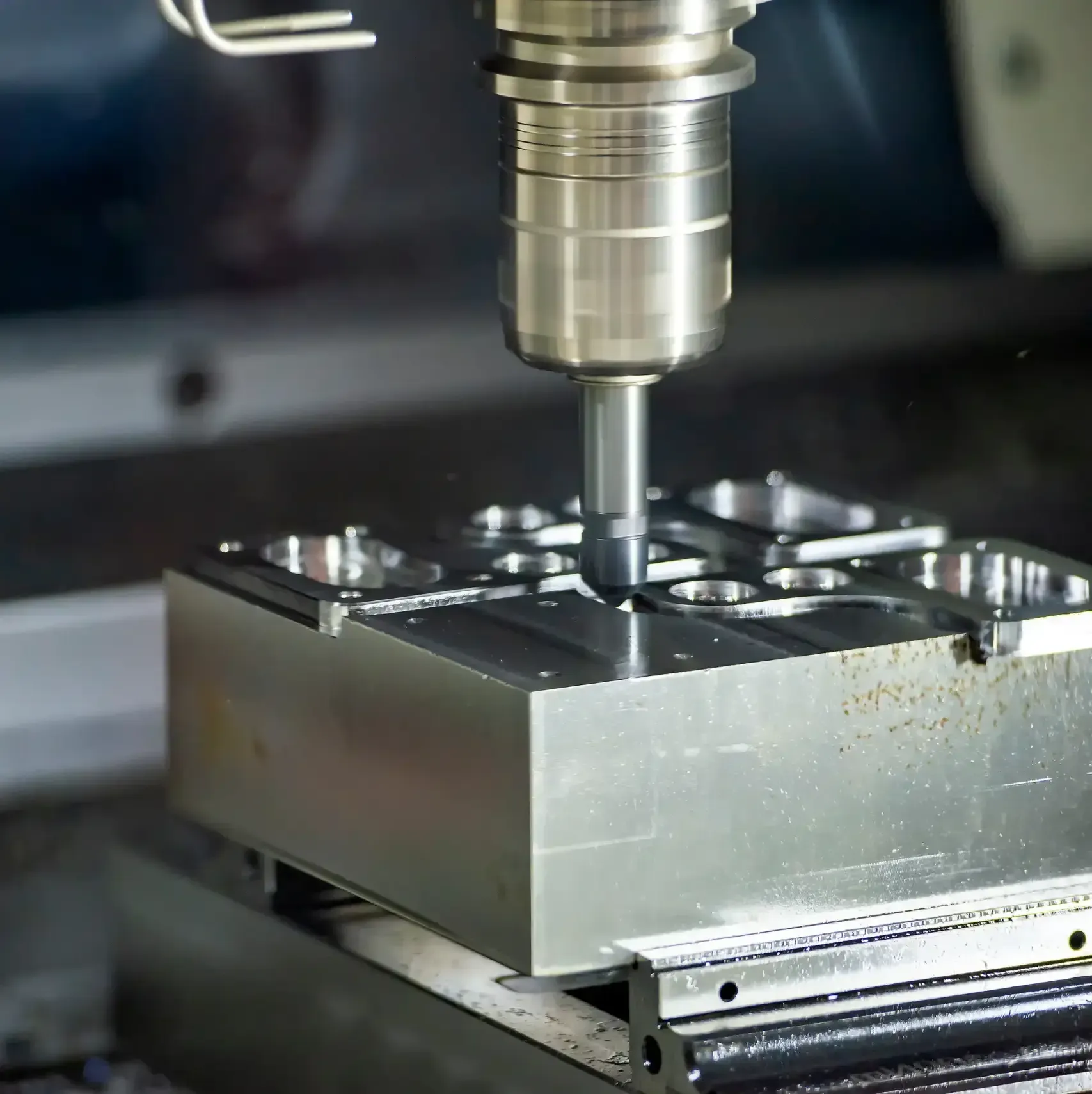
Machine plates, frames, base structures, fixtures, housings and structural parts.

Molds, models, tooling components and large-surface 3D geometries.
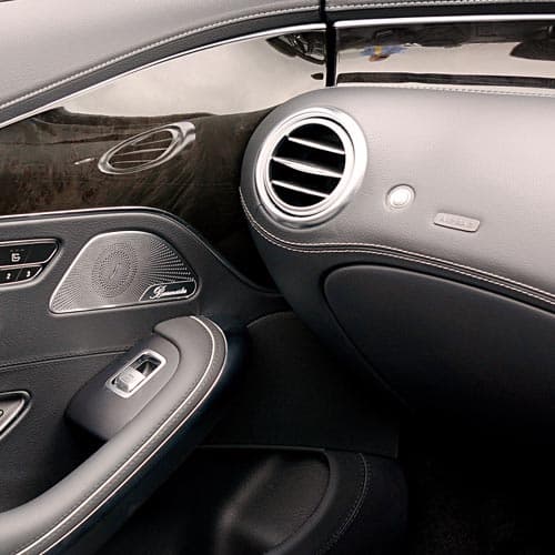
Prototypes, model making, molds, structural parts and fixtures.
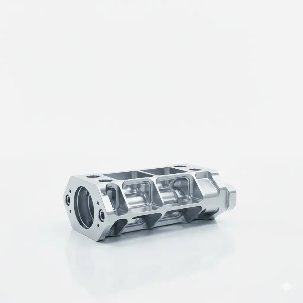
Large, lightweight structural parts – aluminum, CFRP, complex 5-axis geometries and high requirements for process reliability are especially relevant here.

Contract manufacturers often need particularly high flexibility: different materials, changing workpiece sizes, fast retooling and universal clamping technology. The portal machine should therefore not be designed around a single component, but around an economically relevant workpiece spectrum.

Large plates and engineering plastic components can be machined efficiently on portal machines.
The investment cost of a portal milling machine depends strongly on the individual machine concept. For a sound assessment, the purchase price alone should therefore not be the only factor considered.
| Analysis parameter | Impact on Investment | Why |
|---|---|---|
| Working Envelope | High | Determines machine bed, portal size and foundation |
| Machine Rigidity | High | Directly affects material usage and construction |
| 5-Axis Kinematics | High | Additional axes, drives and control technology |
| Spindle Power | Medium to high | Higher power requires stronger drives and cooling |
| Tool Changer | Medium | Additional mechanics and tool magazine |
| Clamping Technology | Medium | Depends on table size and clamping system |
| CNC Control | Medium | Depends on functional scope and number of axes |
| Metrology | Medium | Additional sensors and software |
| Automation | High | Robotics, interfaces and safety technology |
| Custom Engineering | Project-specific | Depends on the individual machine concept |
01
The overall economic cost is made up of, among other things:
02
Payback depends heavily on the production process. If, for example, a new machine solution saves 20 minutes of machining or setup time per component and several thousand components are produced per year, the saved machine and personnel time alone can already produce substantial economic benefits.
A realistic ROI assessment should consider at least current and future machining time, machine hourly rate, annual volume, setup time, personnel, rejects and maintenance.
Machine planning involves more than just the footprint. These factors should be considered as early as possible.
Planning Points to Consider
Floor space: machine plus maintenance and operating areas
Ceiling height: portal and accessibility
Foundation: depends on machine and process
Power supply: connected load
Compressed air: tooling and clamping technology
Cooling system: depends on material
Extraction: especially for plastic, CFRP, wood
Chip disposal: depends on process and material
Transport route: bringing the machine into the facility
Safety: enclosure, doors, light guards
Maintenance access: machine components must remain reachable
Process
A clear flow, one point of contact, and a well-coordinated manufacturing process.
The workpiece, material, geometry, tolerances, quantity, current machining process and target process form the starting point.
Based on this, we define the working envelope, portal design, axis concept, spindle, clamping technology, tooling strategy and automation.
Even before the machine is built, axis travel, tool accessibility, collision spaces, machining positions and cycle times can be examined digitally.
Mechanics, machine and peripherals are coordinated with one another.
Depending on the project, this includes CNC control, safety control, user interface, interfaces, metrology and automation.
The machine is assembled, tested and commissioned.
Before delivery, the agreed functions and requirements are verified.
The machine is installed at the production site and validated again.
On request, we support the transition to productive operation.
A sound machine design starts with a few key pieces of information.
This Information Helps with an Initial Assessment
Material: aluminum, steel, stainless steel, plastic, CFRP, GFRP or other
Workpiece dimensions: length × width × height
Workpiece weight in kg
Required tolerance in mm
Quantity: single part, small batch or series
Machining: 3 axes, multi-side machining or 5 axes
Automation: manual, semi-automated or fully automated
Working envelope, kinematics and spindle are derived from your component – not from brochure values.
We develop the machine, controls and automation as one interconnected system.
What matters is reproducible accuracy in continuous operation.
Simulation clarifies motion sequences and collision risks before the machine is built.
Interfaces and clamping technology are prepared for later automation stages.
Clearly defined from the feasibility study through to acceptance under production conditions.
ISO 9001:2015 certified – requirements and acceptances remain documented.
Maintainability and expandability are factored into the system design from the outset.
FAQ
A portal milling machine is a CNC machine tool in which the milling head is moved within a portal-like structure. This design enables especially large working envelopes and is therefore suitable for large plates, structural parts, machine components and other large-volume workpieces.
A CNC control moves the tool and machine axes along programmed tool paths. Depending on the machine design, either the portal moves over the workpiece, or the workpiece is moved on a machine table beneath the portal.
A portal milling machine is a special design of CNC milling machine. Its characteristic feature is the portal structure, which enables a large working envelope.
"Gantry" refers to a portal-like machine structure. On gantry machines, the portal frequently moves over a stationary or largely static workpiece.
Depending on machine rigidity, spindle and process design, materials such as aluminum, steel, stainless steel, plastic, CFRP, GFRP, wood, foams and model-making materials can be machined, among others.
Yes. However, the machine must be sufficiently rigid and have a spindle, tool holder and cooling suitable for steel. Not every lightweight portal machine is designed for economical steel machining.
The achievable accuracy depends on the machine and the process. Besides positioning accuracy and repeatability, machine rigidity, temperature, tooling, spindle, workpiece clamping and machining strategy all influence the actual component accuracy.
In industrial special-purpose machine building, portal machines can be built with very large travel ranges. The appropriate size depends on the maximum workpiece, the machining process and the available production floor space.
With a moving portal (gantry system), the workpiece remains stationary while the portal moves – this is particularly suitable for heavy, large and long workpieces as well as plate machining, since the workpiece does not need to be moved with high dynamics.
With a fixed portal and a moving table, the workpiece instead moves with the table, and the moving mass increases with the workpiece weight. This design is well suited to more compact workpieces and high process forces, since a very rigid machine structure can be achieved.
This cannot be determined from the material alone. Besides power and torque, speed range, tool holder, spindle bearing, cooling, runout and tool diameter all play a role.
The material also sets the direction: for aluminum, speed, dynamics and chip evacuation matter most; for steel and stainless steel, torque and process stability; for plastic, speed and heat management; and for CFRP/GFRP, the right tool selection and extraction.
Both systems have different strengths. Ball screws offer very high precision but are better suited to limited travel ranges. Rack-and-pinion drives, when of high quality, likewise achieve very high precision and are particularly well suited to long axes, high traverse speeds and large portal machines, while offering greater design flexibility.
Which solution makes sense depends on travel range, required dynamics and machine concept.
Stepper motors are suitable for smaller, less dynamic systems and stand out for their simple technology, low cost and good positionability. Closed-loop systems combine a motorized drive with position feedback, reducing the risk of undetected step loss.
Servo motors are especially suitable for industrial machines with high axis speeds, high dynamics, large masses and demanding automation processes. The right choice depends on mass, acceleration, travel range and process requirements.
Five axes make sense when complex geometries, freeform surfaces or multiple machined sides need to be produced without repeated re-clamping.
A vacuum table is particularly suitable for large-surface plates. T-slot tables are more flexible for clamping straps, fixtures or vises. Depending on the machine, both systems can be combined.
The cost depends strongly on the working envelope, machine rigidity, spindle, axis system, control, clamping technology and automation. For special-purpose machines, the complete manufacturing task should therefore always be evaluated.
Portal milling machines generate high speeds, rotating tools and, depending on the process, large volumes of chips or dust. A safe machine concept therefore typically includes a protective enclosure, interlocked access doors, an emergency stop system, extraction and chip removal, process monitoring, tool breakage monitoring and, where appropriate, light guard systems.
The specific safety design must always be matched to the machine and its intended use.
The process begins with the workpiece and the manufacturing requirements. From these, machine kinematics, working envelope, spindle, clamping technology, automation and controls are derived. Design, digital validation, assembly, commissioning and acceptance follow.
Knowledge hub


Large workpieces, high accuracies or complex production processes require a machine that fits the actual manufacturing task.
Send us your drawing, your 3D model or the key workpiece data. Together with you, we determine which portal design, working envelope, spindle, clamping technology and degree of automation make technical and economic sense for your application.
Trusted by


Book a personal meeting
Contact us now
© assemblean 2026 | All rights reserved.